
Microseismic Monitoring of Northern Alberta Well Casing and Caprock Integrity During Cyclic Steam Stimulation


Microseismic monitoring of well casing and caprock integrity during Cyclic Steam Stimulation in Northern Alberta
Microseismic monitoring of CSS operations in the oil sands in northern Alberta allow for early detection of well casing or caprock damage caused by high temperatures and pressures, helping to mitigate environmental and safety risks during sensitive oil recovery operations.
Cyclic Steam Stimulation (CSS) is a common oil extraction method used in the Cold Lake heavy oil sands in northern Alberta, Canada. The bitumen is located about 450 meters from the surface and well configurations in the area consist of 20-30 deviated production wells drilled from a central location, or well pad.
CSS is a three stage thermal recovery method where steam is first injected into the well at temperatures in excess of 300°C and pressures of 10-12 MPa, heating the oil in the reservoir and reducing the viscosity so that it can flow. The steam is then left to ‘soak’ before production begins.
Challenge
Oil recovery methods in the Alberta oil sands are environmentally sensitive and many risks exist for environmental damage during CSS. Well casings are subject to severe tensile stresses due to the high temperature, high pressure nature of the CSS process. These stresses have the potential to result in mechanical failures such as cement cracks or casing shear leading to well downtime, damaging spills or hazardous blowouts. Shear stresses also develop during the dilation of the reservoir during the steam injection, potentially causing the incursion of fluids into the overlying shales and aquifers above the caprock and causing environmental contamination and costly clean up and regulatory penalties.
The ability to monitor these recovery operations and gain awareness of potentially dangerous or damaging conditions so that remedial actions can be taken is crucial. The ESG real-time microseismic reservoir monitoring systems (ResMap™) have been instrumental in providing such monitoring.
ESG Solution
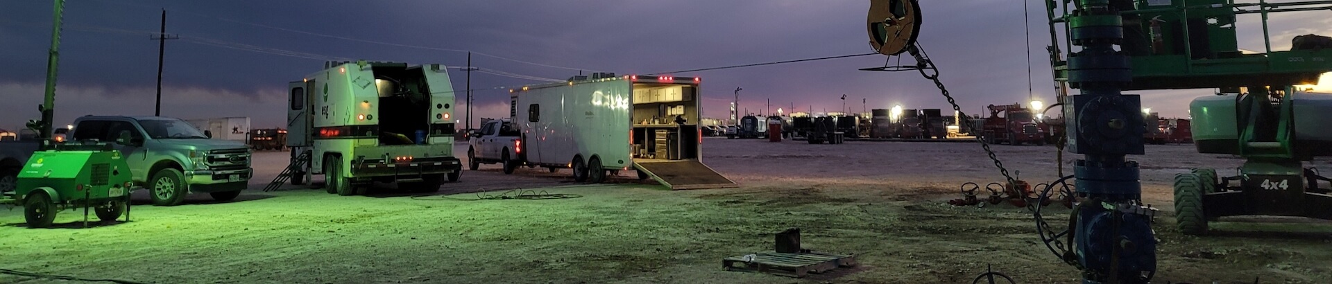
Since 2002 ESG has been responsible for the development and deployment of 2nd generation passive seismic monitoring systems and analytical techniques designed to detect the microseismicity associated with well casing failure and caprock breaches. These real-time reservoir monitoring systems have been deployed for multiple clients with operations in the Cold Lake Region, acting as an early warning system to potentially hazardous events and allowing for visualization of event locations.
Downhole multi-level (between 5-10) dual 3-component sensor arrays are cemented into monitoring wells located near the center of the CSS well pads. ESG’s 24-bit digital Paladin™ data acquisition units are placed at the well head to record the microseismicity occurring around the well casing and caprock. The microseismic event data are transmitted via DSL/Fiber optic cable to a centralized computer station where automatic processing characterizes the events and identifies potential well casing shear or cement cracking based on criteria involving event thresholds of P/S, Sh/Sv and R*PPV. ResMap™ alerts operators of any occurrences of suspected dangerous events via emails, cell phones or pagers.
Outcome
The ESG ResMap™ systems monitor CSS operations 24/7 for the life of the field operations and acts as an early warning system, giving operators the chance to react in real-time in the event a failure or breach occurs.
Clients within the Cold Lake Region have been able to demonstrate environmental due diligence and ensure their operations are complying with regulatory directives. Producers have also been able to decrease well downtime, and develop response strategies to check wells which have experienced a heighted amount of microseismic activity. Clients may also use the information obtained from a monitoring system to adjust their steaming strategies to reduce the number of failures that may be taking place during certain phases.


